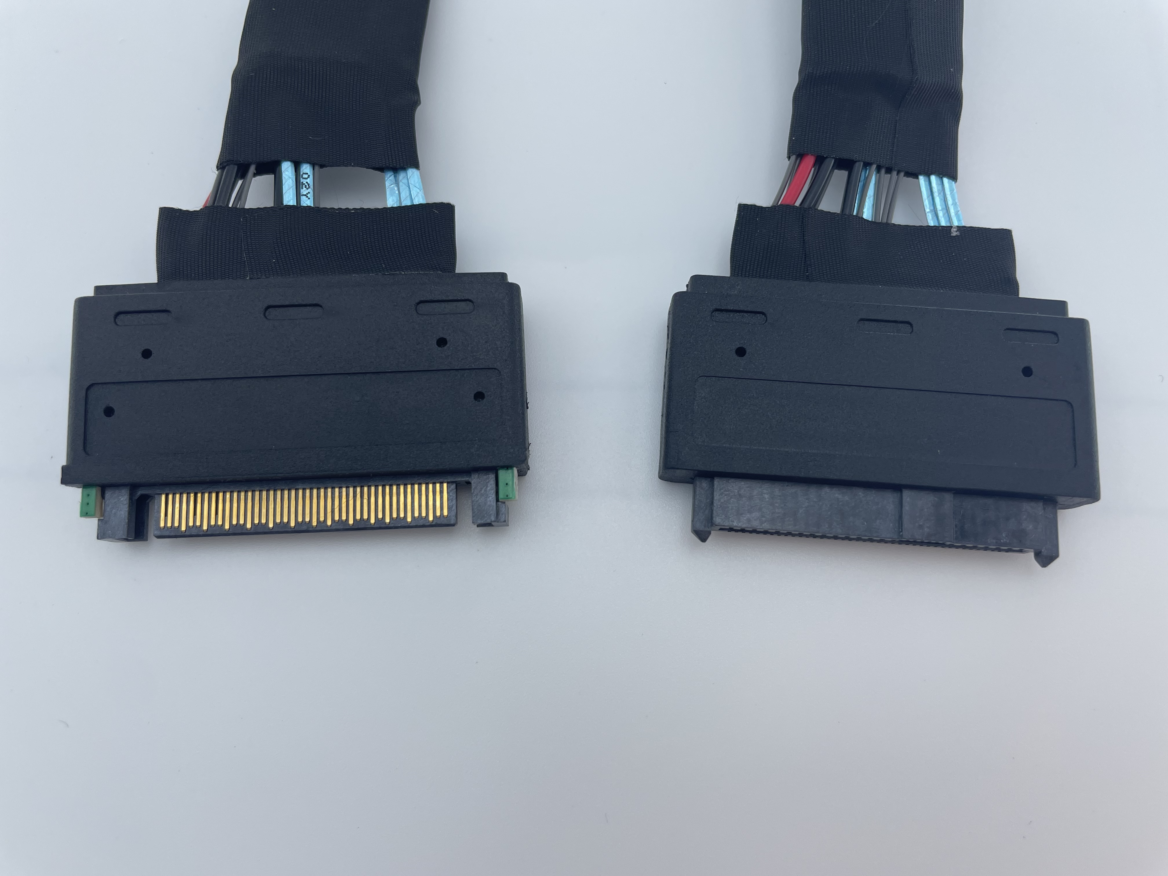
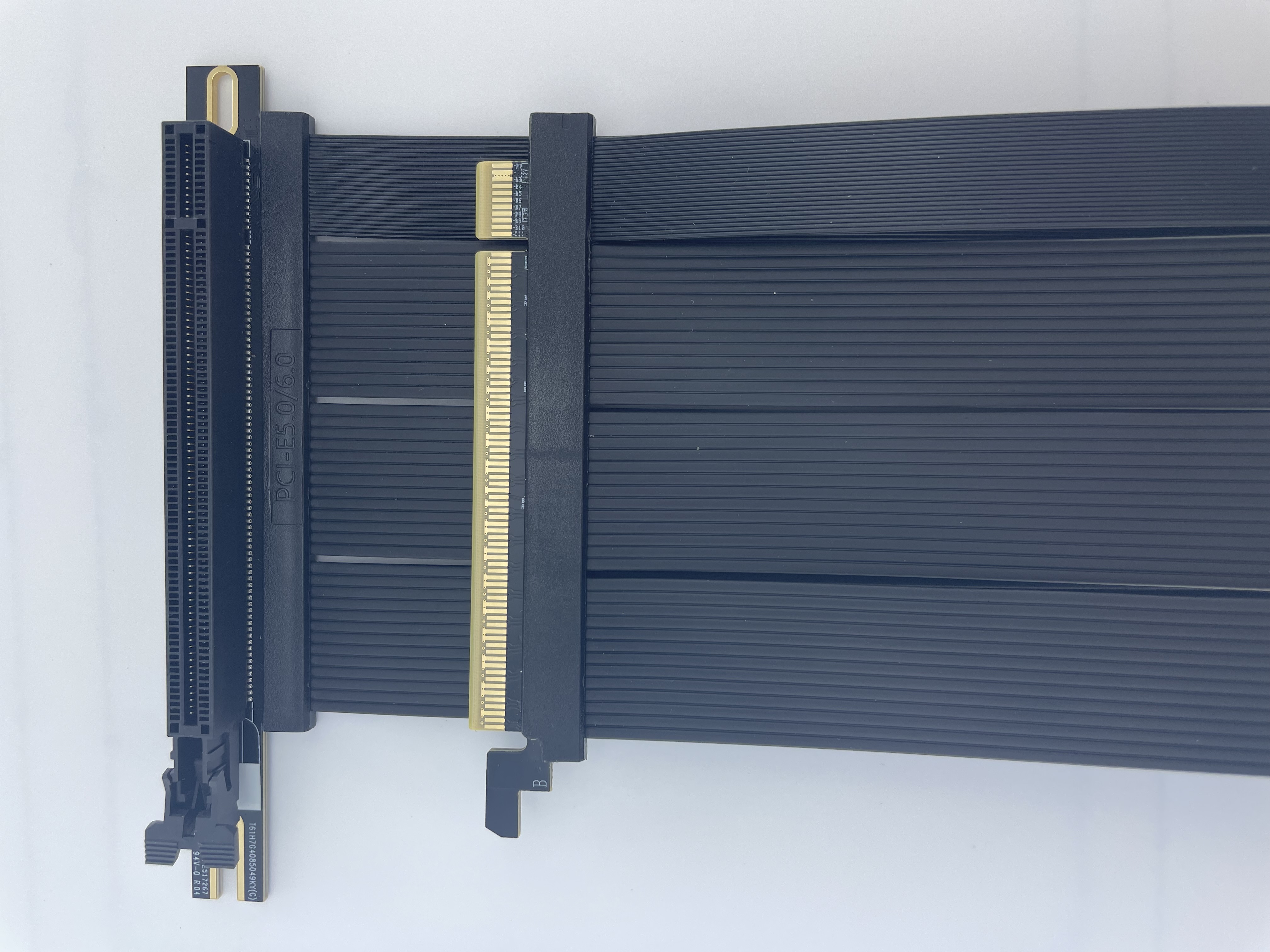
T1070I7J12502 — This assembly combines two MCIO branches with a CEM slot board and a separate 3.0 mm 4-pin power connection. Specify the route length of each signal branch and the power branch independently.
Application and selection
Use it to route dual MCIO paths to a CEM card position within a specified system. Check the lane order of both branches, clock/reset and other sideband signals, and the source of slot power. Include card support and branch strain relief in the installation plan.
Interface and installation requirements
PCIe 6.0 is the nominal series designation; validate the intended link for the selected length and system. A separate power branch must match the slot-board wiring. It does not establish a higher slot power rating or replace the dedicated auxiliary power required by an expansion card.
Drawing-based factory assessment
Provide host and card models, MCIO port definitions, P1/P2 mapping, the power pin table, each branch length and mounting drawing. Suntecc can assess lengths, terminations and production requirements against the drawings. Define voltage assignments and branch functions for the system before approving the configuration.
During sample assembly, review mating, fastening, routing and removal in sequence, then record the selected configuration as a drawing revision for repeat orders. Measure length along the actual route and include connector access, rather than ordering solely from the straight-line distance between the two mating points. Record the connector orientation at each end so repeat orders use the same installation reference.
Discuss this cable assembly · Browse this product category